How to Build a Custom Mobile Communication Device with ESP32
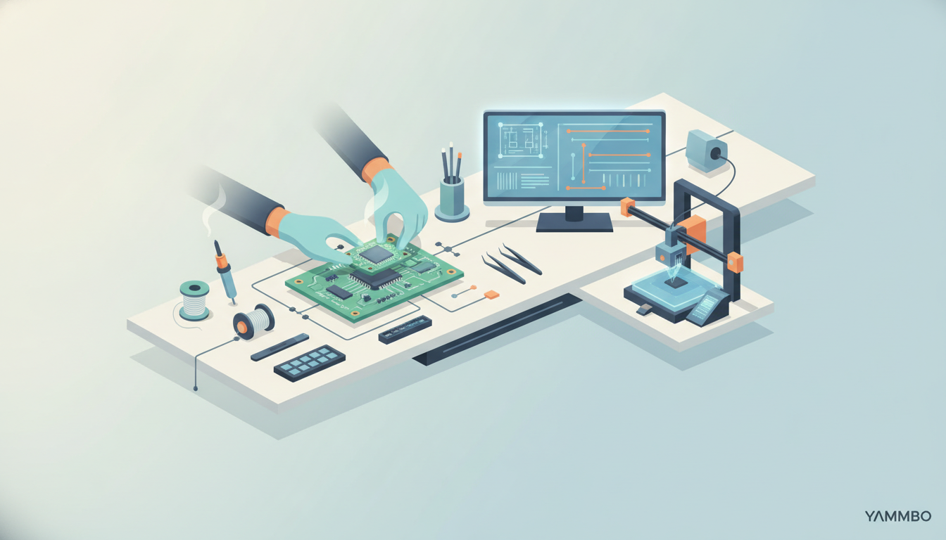
Understanding the intricate workings of a mobile phone often feels like a daunting task, yet the core principles of embedded systems and mobile communication are accessible to anyone willing to explore. This tutorial demystifies the process by guiding you through the creation of a custom communication device. We'll cover everything from selecting the right components and assembling them without soldering to programming its functionality using popular embedded development frameworks. By the end, you'll have a deeper appreciation for the technology that underpins our daily communications.
Step 1: Understanding the Core Components of Your Device
Before you begin assembly, it's crucial to understand the purpose of each major component in your custom communication device. Each part plays a vital role in enabling its functionality, from processing information to connecting to cellular networks.
The Microcontroller: ESP32-S3
At the heart of many DIY projects, including this one, is a powerful yet low-power microcontroller like the ESP32-S3. This dual-core processor is equipped with integrated Wi-Fi and Bluetooth capabilities, making it ideal for connected projects. It handles all the computational tasks, processes user input, manages the display, and communicates with the cellular module. Its generous flash memory (typically 4 MB) and PSRAM (also 4 MB) provide ample space for complex applications and data.
Cellular Module: 4G LTE Cat-1
To enable calls and texts, your device needs a cellular module. A 4G LTE Cat-1 module is a common choice for embedded systems due to its balance of speed and power efficiency, offering reliable data rates suitable for communication without the high power demands of full-fledged 5G. These modules typically support a Nano SIM card and often include 2G fallback for areas with limited 4G coverage. Communication with the cellular module is usually done via AT commands over a serial interface.
Display and Input
- Display: A small color LCD, often around 1.77 inches with a resolution like 160x128 pixels, provides visual feedback. These displays typically connect via SPI (Serial Peripheral Interface) and require specific libraries for graphics rendering.
- Input: A 12-key numeric keypad, a navigational joystick, and a few function keys allow for user interaction. These inputs are usually read by scanning GPIO (General Purpose Input/Output) pins on the microcontroller.
Audio, Power, and Storage
- Audio: A Digital-to-Analog Converter (DAC) drives a small speaker for audio output, while an I²S (Inter-IC Sound) microphone enables audio input for calls. A 3.5mm headphone jack offers private listening.
- Battery: A rechargeable lithium-ion battery (e.g., 1000 mAh) powers the device, charged via a USB-C port, which also serves for data transfer and programming.
- Storage: A microSD card slot provides expandable storage for applications, contact lists, and other data.
Connectivity and Expansion
Beyond cellular, the ESP32-S3 provides Wi-Fi and Bluetooth for local connectivity. Many DIY phone kits also include modular connectors (e.g., UMAX) that allow for easy addition of extra hardware, expanding the device's capabilities without complex wiring.
Step 2: Assembling Your Hardware: A No-Solder Approach
One of the most appealing aspects of modern DIY electronics is the ability to assemble complex devices without the need for soldering. This step focuses on connecting the various components using pre-fabricated connectors, making the process accessible and less prone to error.
Gathering Your Components
Ensure you have all the necessary parts: the main circuit board (housing the ESP32-S3 and cellular module), the display, keypad, battery, speaker, microphone, and any additional modules you plan to integrate. Most kits come with a detailed assembly guide, which you should follow closely.
Connecting the Core Elements
- Main Board Preparation: Start with the main circuit board. Identify the various connectors for the display, keypad, cellular antenna, battery, and other peripherals.
- Display Connection: Carefully align the display's flexible flat cable (FFC) or pin header with its corresponding connector on the main board. Gently push it into place, ensuring it's seated firmly. Many FFC connectors have a small latch that needs to be opened before insertion and closed afterward.
- Keypad and Input: Connect the keypad's cable to its designated port. If there's a joystick or additional function keys on a separate board, connect those as well. These usually use simple pin headers or small ribbon cables.
- Cellular Module Integration: Insert the Nano SIM card into the cellular module's tray. Connect the cellular antenna to the module, ensuring it's securely fastened. Then, connect the cellular module to the main board, often via a dedicated connector or a set of pins.
- Battery and Power: Connect the battery to its JST connector on the main board. Pay close attention to polarity if the connector isn't keyed to prevent damage.
- Audio Components: Attach the speaker and microphone to their respective connectors. These are typically small, two-pin connectors.
Enclosure Assembly
Once all internal components are connected, carefully place them into the device's enclosure. Ensure cables are routed neatly and don't get pinched. Secure the back panel or casing with screws, if applicable.
Verification
After assembly, connect the device to a USB-C power source. The display should show some sign of life, perhaps a boot logo or a blank screen with backlighting. This confirms that the basic power and display connections are functional. If nothing appears, double-check all connections, especially the battery and display.
Step 3: Setting Up the Development Environment for Embedded Systems
With your hardware assembled, the next step is to prepare your computer for programming the ESP32-S3. This involves installing drivers, an Integrated Development Environment (IDE), and the necessary board support packages.
Installing USB-to-Serial Drivers
The ESP32-S3 communicates with your computer over a serial connection, typically via a USB-to-serial converter chip (like CP210x or CH340) on the development board. You'll need to install the appropriate drivers for your operating system. You can usually find these on the manufacturer's website (e.g., Silicon Labs for CP210x, WCH for CH340).
# Example command for macOS (using Homebrew) for CP210x drivers:brew install --cask silicon-labs-vcp-driverVerification: After installation, connect your device to your computer via USB-C. Open your computer's device manager (Windows) or run ls /dev/tty.* (macOS/Linux) to confirm a new serial port (e.g., COMx or /dev/ttyUSB0) appears.
Choosing and Installing an IDE
Two popular choices for ESP32 development are the Arduino IDE and Visual Studio Code with PlatformIO.
- Arduino IDE: Simple and beginner-friendly. Download it from the official Arduino website.
- Visual Studio Code with PlatformIO: More powerful, offering advanced features like intelligent code completion, debugging, and support for multiple frameworks. Download VS Code, then install the PlatformIO IDE extension from the Extensions marketplace.
Installing ESP32 Board Support
Regardless of your chosen IDE, you need to add support for ESP32 boards.
- Arduino IDE:
- Go to
File > Preferencesand addhttps://raw.githubusercontent.com/espressif/arduino-esp32/gh-pages/package_esp32_index.jsonto "Additional Board Manager URLs." - Go to
Tools > Board > Board Manager..., search for "ESP32," and install the "esp32 by Espressif Systems" package. - Select your specific ESP32-S3 board from
Tools > Board > ESP32 Arduino.
- Go to
- PlatformIO (VS Code):
- Create a new PlatformIO project.
- When prompted, select your specific ESP32-S3 board (e.g., "ESP32-S3-DevKitC-1"). PlatformIO will automatically install the necessary toolchain and frameworks.
Verification: In Arduino IDE, try compiling a simple "Blink" example for your selected ESP32-S3 board. In PlatformIO, ensure your project builds without errors.
Step 4: Programming Your Device: MicroPython and Arduino C++
Now that your development environment is ready, you can start writing code to bring your device to life. We'll explore two primary programming options: MicroPython for quick prototyping and Arduino C++ for more performance-critical applications.
Option A: Programming with MicroPython
MicroPython is a lean and efficient implementation of the Python 3 programming language optimized to run on microcontrollers. It's excellent for rapid development and offers an interactive REPL (Read-Eval-Print Loop) for immediate testing.
- Install MicroPython Firmware: You'll first need to flash the MicroPython firmware onto your ESP32-S3. Download the appropriate
.binfile from the MicroPython downloads page. Use a tool likeesptool.pyto flash it:pip install esptoolesptool.py --chip esp32s3 erase_flashesptool.py --chip esp32s3 write_flash -z 0x0 PATH_TO_YOUR_MICROPYTHON.bin - Install Thonny IDE: Thonny is a user-friendly Python IDE with built-in MicroPython support, making it easy to connect to your device, upload scripts, and interact with the REPL.
- Write a Basic Script: In Thonny, connect to your ESP32-S3 via the serial port. You can then write and upload simple scripts. For example, to make an LED blink (assuming one is connected to GPIO 2):
import machineimport timeled = machine.Pin(2, machine.Pin.OUT)while True: led.value(1) # Turn LED on time.sleep(0.5) led.value(0) # Turn LED off time.sleep(0.5) - Interacting with Hardware: For the display and keypad, you'd typically use specific MicroPython libraries (e.g.,
micropython-ili9341for displays, custom drivers for keypads) which you can upload to the device's filesystem using Thonny orampy.
Verification: Upload a simple script that prints "Hello, DIY Phone!" to the serial console. If using a display, try displaying text on it. Ensure the script runs without errors and you see the expected output.
Option B: Programming with Arduino C++
Arduino C++ (or the Arduino framework for ESP32) provides a familiar environment for many hardware enthusiasts, offering a vast ecosystem of libraries for various components. It generally offers better performance and lower-level control compared to MicroPython.
- Open Arduino IDE or PlatformIO: Start a new sketch (Arduino IDE) or project (PlatformIO).
- Include Libraries: For display, keypad, and cellular modules, you'll need to include specific libraries. Common ones include
Adafruit_GFXand a display-specific library (e.g.,TFT_eSPI) for graphics, andTinyGSMfor cellular communication. Install these via the Arduino Library Manager or PlatformIO's library installer. - Basic Sketch Structure: An Arduino sketch has two main functions:
setup()(runs once at startup) andloop()(runs continuously).#include <Arduino.h>// Include your display, keypad, cellular libraries herevoid setup() { Serial.begin(115200); // Initialize display, keypad, cellular module Serial.println("Device Starting...");}void loop() { // Read keypad input // Update display // Handle cellular communication} - Upload Code: Select the correct serial port and board in your IDE, then click the "Upload" button.
Verification: Upload a sketch that initializes the serial port and prints a message. Open the Serial Monitor in your IDE to confirm the message appears. Try a basic display example to show text on the screen.
Step 5: Implementing Basic Communication Features
With your device programmed, the next crucial step is to enable its core function: mobile communication. This involves interacting with the cellular module to send SMS messages and make calls.
Understanding AT Commands
Cellular modules are typically controlled using a set of text-based commands called AT commands (Attention commands). These commands are sent over a serial interface to the module, which then executes them and returns a response. While libraries often abstract these, understanding the basics is helpful.
AT: Tests the connection to the module. Expected response:OK.AT+CSQ: Checks signal quality.AT+CMGF=1: Sets SMS message format to text mode.AT+CMGS="<phone_number>": Sends an SMS. After this, you send the message text, followed byCtrl+Z(ASCII 26).ATD<phone_number>;: Dials a phone number.
Sending an SMS Message (Arduino C++ Example with TinyGSM)
Using a library like TinyGSM simplifies interaction with the cellular module significantly.
#include <TinyGSM.h>#include <SoftwareSerial.h> // Or use HardwareSerial if availableconst int RX_PIN = 16; // Connect to modules TX_PINconst int TX_PIN = 17; // Connect to modules RX_PINSoftwareSerial GSM_Serial(RX_PIN, TX_PIN);TinyGSM modem(GSM_Serial);void setup() { Serial.begin(115200); GSM_Serial.begin(115200); // Baud rate for your GSM module Serial.println("Initializing modem..."); modem.init(); Serial.println("Waiting for network..."); if (modem.waitForNetwork()) { Serial.println("Network connected!"); } else { Serial.println("Network not connected."); } Serial.println("Sending SMS..."); if (modem.sendSMS("+1234567890", "Hello from my custom phone!")) { Serial.println("SMS sent successfully!"); } else { Serial.println("Failed to send SMS."); }}void loop() { // Your main application logic here}Making a Voice Call (Arduino C++ Example with TinyGSM)
// ... (setup from above) ...void loop() { // ... (existing loop logic) ... static bool callMade = false; if (!callMade) { Serial.println("Making a call..."); if (modem.call("+1234567890")) { Serial.println("Call initiated. Waiting for answer..."); // You might add logic here to detect call status // For simplicity, we'll just hang up after a few seconds delay(10000); // Wait 10 seconds modem.hangup(); Serial.println("Call ended."); callMade = true; } else { Serial.println("Failed to make call."); } } delay(1000); // Prevent rapid re-attempts}Verification: Insert a working Nano SIM card into your cellular module. Upload the SMS sending code and check if the message is received on the target phone. For calls, upload the calling code and observe if the target phone rings. Ensure you have sufficient credit or an active plan on the SIM card.
Step 6: Expanding Functionality with Modules and AI-Assisted Development
The modular design of many DIY communication devices allows for significant expansion beyond basic calls and texts. Furthermore, artificial intelligence (AI) tools, particularly large language models (LLMs), can significantly accelerate the development process for these added functionalities.
Integrating Additional Hardware Modules
Your device's expansion connectors open up a world of possibilities. Common modules include:
- Infrared (IR) Module: Allows your device to act as a universal remote control for TVs or other IR-enabled appliances. These typically connect via a single GPIO pin.
- Camera Module: Enables basic photography or video capture. Camera modules often use specific interfaces like DVP (Digital Video Port) or SPI, requiring dedicated drivers.
- Additional Speaker Module: A more powerful speaker (e.g., 2W) for louder audio output, useful for music playback or alarms.
- Environmental Sensors: Modules like temperature and humidity sensors (e.g., DHT11, BME280) or light sensors can turn your device into a portable monitoring station. These often communicate via I2C or SPI.
- Perfboard Module: A blank prototyping board allows you to wire in your own custom sensors or circuits, offering ultimate flexibility.
Integrating these modules typically involves connecting them to the appropriate pins (GPIO, I2C, SPI) on your main board and then writing software to communicate with them using their specific protocols and libraries.
Leveraging AI for Code Generation and Assistance
AI-powered coding tools, often based on large language models, can be invaluable when adding new features or working with unfamiliar hardware. They can:
- Generate Boilerplate Code: Need to read data from a specific sensor? Describe the sensor and the microcontroller (e.g., "MicroPython code for ESP32-S3 to read a DHT11 temperature and humidity sensor"), and the LLM can provide a starting point.
- Suggest Libraries: If you're unsure which library to use for a particular display or module, an LLM can often point you to popular and well-maintained options.
- Debug and Explain Code: Paste a snippet of code that isn't working, and the LLM can help identify potential errors or explain complex sections.
- Convert Code: If you find an example in Arduino C++ but want to use MicroPython, an LLM can often assist in translating the logic.
While AI tools can significantly lower the barrier to entry and speed up development, it's important to understand the generated code. Always review, test, and adapt the AI's output to ensure it meets your specific requirements and works correctly with your hardware.
Verification: If integrating a sensor, write a small program to read its values and display them on the screen or print them to the serial monitor. If using an IR module, try sending a known IR code to a TV to confirm it responds.
Conclusion
Building your own mobile communication device is an incredibly rewarding journey that offers deep insights into the world of embedded systems, hardware assembly, and programming. From understanding the core components and meticulously assembling them without soldering, to writing firmware in MicroPython or Arduino C++ and enabling cellular functions, you've gained practical experience with the technologies that power our modern world. This hands-on approach not only equips you with valuable technical skills but also fosters a deeper appreciation for the engineering behind everyday devices. For those looking to build and customize their online presence, explore the tools available at Yammbo Web.